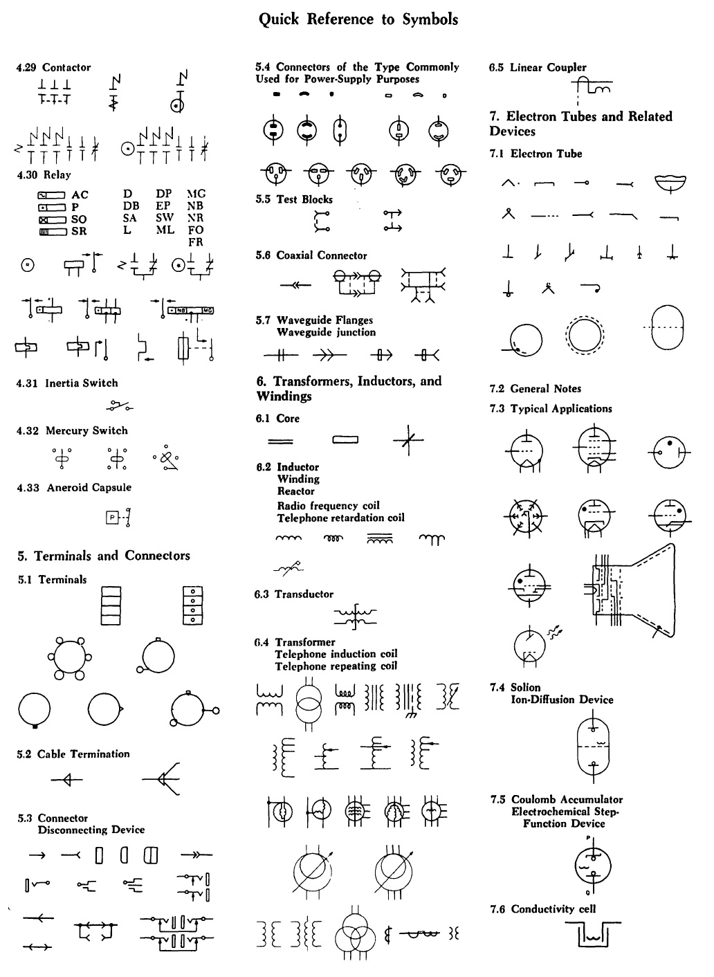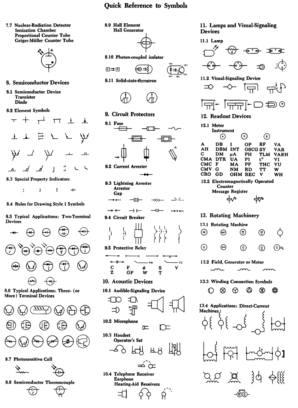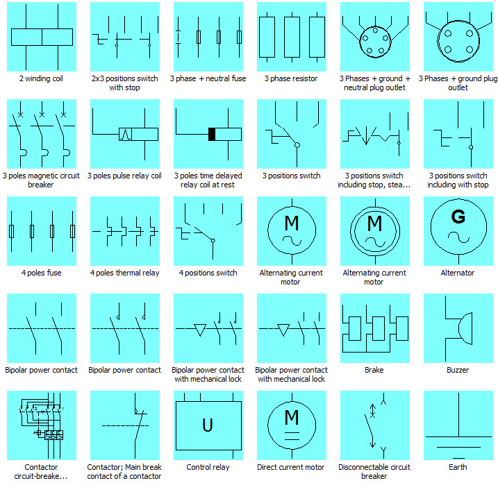
Ever wondered what those cryptic symbols on electrical diagrams represent? They're not hieroglyphics, but a standardized language crucial for electrical engineers and technicians worldwide. Understanding these symbols is paramount for safe and efficient electrical system design, installation, and maintenance. This revolves around the International Electrotechnical Commission (IEC) standards for electrical symbols.
These internationally recognized symbols provide a common visual language for electrical systems. Imagine trying to decipher a circuit diagram with arbitrary, inconsistent symbols – chaos would ensue! The IEC standards establish uniformity, ensuring that an engineer in Japan can readily interpret a schematic drawn by an engineer in Brazil. This shared understanding reduces the risk of misinterpretations, errors, and ultimately, accidents.
The IEC, founded in 1906, plays a vital role in developing and publishing international standards for all electrical, electronic, and related technologies. Their work on standardizing electrical symbols began decades ago, evolving over time to incorporate new technologies and improve clarity. These standards, specifically IEC 60617, are regularly updated to reflect advancements in the field, ensuring relevance and accuracy.
One of the primary challenges with electrical symbols is the sheer number and complexity. Remembering the specific representation for each component can be daunting. However, resources such as IEC publications, specialized software, and online databases are available to aid in both learning and implementing these standards effectively. Consistent use and practical application are key to mastering this symbolic language.
The importance of adhering to IEC standards cannot be overstated. They are fundamental for safety, ensuring that everyone working with electrical systems speaks the same visual language. This shared vocabulary facilitates effective communication, collaboration, and problem-solving, ultimately leading to safer and more efficient electrical systems.
These symbols represent various electrical components, like resistors, capacitors, switches, and transformers. For example, a resistor is symbolized by a zig-zag line, while a capacitor is represented by two parallel lines. These simplified graphical representations make complex circuit diagrams easier to understand and analyze.
Benefits of adopting IEC electrical symbol standards include improved communication, reduced errors in design and installation, and enhanced safety. Using universally recognized symbols helps prevent costly mistakes and ensures everyone working on a project is on the same page. This contributes to efficient project completion and safe operation of electrical systems. Imagine the potential hazards if different symbols were used for the same component – misinterpretations could lead to serious safety risks.
To implement these standards effectively, create a component library using IEC symbols, train personnel on their use, and regularly review diagrams for compliance. Using dedicated software can assist in creating and managing these libraries, ensuring consistent application across all projects.
Advantages of using IEC symbols include global understanding and improved safety. Disadvantages may include the initial learning curve and the need for resources to access the standards.
Best practices for IEC symbol implementation include using the latest edition of the standard, ensuring consistent application across all projects, and providing training to all personnel. Utilizing specialized software that incorporates the IEC library can streamline the design process and ensure compliance.
Real-world examples of IEC symbol usage can be found in building schematics, industrial automation diagrams, and electronic circuit designs. These symbols are essential in these applications for clear communication and safe operation of the systems.
Frequently asked questions about IEC standards include "Where can I find the latest IEC standards?", "What software supports IEC symbols?", and "How often are the standards updated?". Answers to these questions can readily be found on the IEC website and other relevant resources.
Tips for using IEC symbols effectively include establishing a company-wide standard, providing regular training, and leveraging software tools. These practices contribute to consistent and accurate use of the symbols, ensuring clear communication and minimizing errors.
In conclusion, the IEC standards for electrical symbols are a cornerstone of the electrical engineering world. They provide a common language that fosters clear communication, reduces errors, and enhances safety in electrical systems. Understanding and correctly applying these standards is essential for anyone involved in the design, installation, or maintenance of electrical systems. By embracing these standards, we contribute to a safer and more efficient electrical landscape worldwide. Investing time and resources in learning and implementing IEC standards is not just good practice – it's a crucial step towards ensuring safety and efficiency in the world of electrical engineering. Explore the resources available, stay up-to-date with the latest revisions, and make the commitment to using IEC standards in your electrical projects. The benefits far outweigh the initial effort, and the impact on safety and clarity is invaluable.
Unlocking physics insights through lab report discussions
Decoding the gs pay scale navigating federal salaries in dc
Finding peace on the road exploring the certified toyota rav4 hybrid


