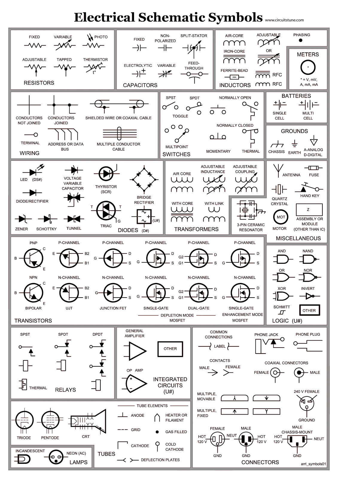
Ever wondered how HVAC technicians quickly diagnose and fix complex systems? The secret lies in their ability to decipher the language of HVAC electrical schematic symbols. These symbols, often compiled into handy PDF documents, act as a roadmap for understanding the electrical intricacies of heating, ventilation, and air conditioning systems. Mastering these symbols is essential for anyone working with HVAC equipment, from seasoned professionals to aspiring technicians.
HVAC electrical schematic diagrams provide a visual representation of the electrical connections and components within a system. They showcase everything from power sources and transformers to motors, relays, and control circuits. Imagine trying to troubleshoot a faulty thermostat without a clear understanding of its wiring. A schematic diagram, with its standardized symbols, provides the clarity needed to effectively diagnose and repair the issue. This visual language simplifies complex systems, making them accessible and manageable.
The use of standardized symbols in HVAC electrical schematics has a rich history, evolving alongside the development of HVAC technology itself. Initially, diagrams might have been rudimentary sketches, but as systems became more complex, the need for a universal language arose. This led to the standardization of symbols, ensuring that technicians everywhere could interpret diagrams regardless of the specific manufacturer or system. This standardization also facilitates efficient communication and collaboration among professionals.
Access to HVAC electrical schematic symbols, often in convenient PDF format, is invaluable for several reasons. They are essential for troubleshooting and repair, enabling technicians to quickly identify faulty components or wiring issues. They're also crucial for system design and installation, allowing engineers to plan and implement efficient and safe HVAC systems. Moreover, these diagrams play a critical role in training and education, providing a visual learning tool for understanding the complex interplay of electrical components within HVAC systems.
One of the main issues related to HVAC electrical schematic symbols is keeping up with evolving technology and standards. As new components and control systems emerge, so do new symbols and diagram conventions. Staying current with these changes is vital for technicians and engineers to effectively utilize schematics and ensure accurate interpretations. This often involves continuous learning and accessing updated resources, like comprehensive PDF compilations of HVAC electrical schematic symbols.
A simple example is the symbol for a thermostat. It's typically represented by a circle with a diagonal line through it. This simple symbol conveys a wealth of information, indicating the presence and location of a temperature control device within the system. Understanding this symbol, along with others, is fundamental to interpreting an HVAC electrical schematic.
One benefit of using HVAC electrical schematic symbols PDFs is portability. Technicians can easily carry these digital documents on their tablets or smartphones, providing instant access to critical information in the field. Another advantage is the searchability of digital PDFs. Keywords can be used to quickly locate specific components or sections within a complex diagram, saving valuable time during troubleshooting. Finally, PDFs are easily shareable, facilitating collaboration among team members or with remote experts.
To effectively utilize HVAC schematics, start by familiarizing yourself with the standard symbols. Numerous resources are available online and in textbooks. Then, practice reading and interpreting diagrams of varying complexity. Finally, apply your knowledge in real-world scenarios, using schematics to troubleshoot and understand existing systems.
Advantages and Disadvantages of Using HVAC Electrical Schematic Symbols PDF
| Advantages | Disadvantages |
|---|---|
| Portability and accessibility on various devices. | Requires software or apps to view and potentially edit. |
| Searchable content for quick access to specific information. | Can be difficult to navigate in very large files. |
| Easy sharing and collaboration among team members. | Printing large schematics can be cumbersome and expensive. |
Best practices for using HVAC electrical schematics include: always refer to the latest version of the diagram, ensure the diagram matches the specific system you're working on, and understand the scale and orientation of the drawing. Additionally, pay attention to any notes or annotations on the schematic and always double-check your interpretations before making any modifications to the system.
Frequently asked questions include: Where can I find HVAC schematic symbols PDFs? What are the most common symbols used in HVAC diagrams? How do I interpret a complex HVAC schematic? How can I stay updated with the latest symbol standards?
In conclusion, HVAC electrical schematic symbols, often compiled into convenient PDF documents, are indispensable tools for anyone working with HVAC systems. They provide a clear and concise visual language for understanding complex electrical circuits, facilitating efficient troubleshooting, design, and installation. Mastering these symbols is essential for professional success in the HVAC industry, ensuring safe and effective operation of these vital systems. By utilizing the available resources, including online PDFs and training materials, you can unlock the power of HVAC schematics and enhance your expertise in this ever-evolving field. Investing time in understanding these diagrams translates to greater efficiency, accuracy, and ultimately, success in the HVAC world. So, dive into the world of HVAC electrical schematics, and empower yourself with the knowledge to confidently navigate the intricacies of these essential systems.
Unlocking opportunities mastering the malaysian job application form pdf
Finding joy exploring the world of happys place tv show
Vanilla ice cream paint the scoop on this delicious trend


