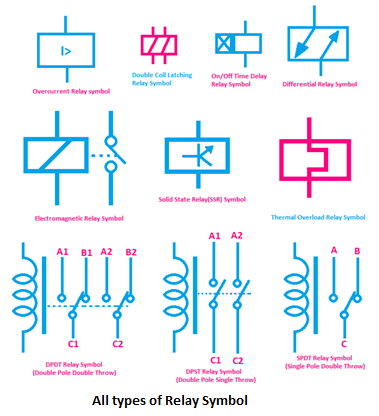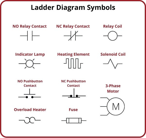
Imagine a tiny switch controlling a powerful circuit – that's the essence of a relay. And at the heart of this electromechanical marvel lies the relay coil, represented by a specific symbol in electrical diagrams. Understanding this symbol is crucial for anyone working with circuits, from hobbyists to seasoned engineers. This article dives deep into the world of the relay coil electrical symbol, unraveling its meaning, history, and practical implications.
The relay coil electrical symbol is more than just a squiggle on a diagram; it represents the electromagnetic component that energizes the relay, allowing it to switch between circuits. This symbol, often depicted as a looped line or inductor symbol, is essential for accurate circuit design and interpretation. Without it, deciphering complex schematics would be significantly more challenging. So, why is this symbol so important? It acts as a universal language, enabling clear communication between engineers and technicians worldwide.
The origins of the relay coil symbol are intertwined with the development of electrical engineering itself. Early relay designs used bulky electromagnets, and their symbolic representation evolved alongside the technology. As relays became smaller and more sophisticated, so did their symbols, eventually leading to the standardized forms we see today. These symbols are a testament to the evolution of electrical engineering and the constant pursuit of efficiency and miniaturization.
The importance of the relay coil symbol becomes clear when we consider its role in circuit analysis and troubleshooting. Identifying the coil allows us to quickly understand the control logic of a circuit and diagnose potential problems. For instance, a malfunctioning coil could prevent a relay from switching, leading to system failures. By understanding the symbol, we can pinpoint the source of the issue and take corrective action.
Variations in the relay coil symbol can indicate specific relay types or configurations. For example, the presence of a diode across the coil signifies a flyback diode, used to suppress voltage spikes. Recognizing these variations is vital for interpreting complex diagrams accurately. Understanding the nuances of the relay coil symbol empowers us to analyze circuits with greater precision and efficiency.
A relay coil, essentially an electromagnet, energizes when current passes through it. This magnetism then activates the relay's switch mechanism. A simple example: imagine a relay controlling a high-power motor. A small current through the relay coil can switch the motor on or off, providing electrical isolation and safety.
Benefits of Understanding the Relay Coil Symbol:
1. Clear Circuit Interpretation: Quickly identify the controlling element within a circuit.
2. Efficient Troubleshooting: Pinpoint potential coil-related issues like open circuits or shorts.
3. Effective Circuit Design: Correctly incorporate relays into new circuits with proper coil considerations.
Advantages and Disadvantages of Using Relays
Advantages and Disadvantages of Using Relays
| Advantages | Disadvantages |
|---|---|
| Electrical Isolation | Slower switching speeds compared to solid-state devices |
| Ability to switch high voltages/currents with low control signals | Mechanical wear and potential failure over time |
| Relatively inexpensive | Can generate audible clicks during operation |
Best Practices for Implementing Relays:
1. Choose the right relay: Consider voltage, current, and switching speed requirements.
2. Protect the coil: Use a flyback diode to suppress voltage spikes.
3. Proper wiring: Ensure correct connections to avoid malfunctions.
4. Consider environment: Temperature, humidity, and vibration can affect relay performance.
5. Regular testing: Check for proper operation and contact wear.
Frequently Asked Questions:
1. What does the relay coil symbol look like? (Answer: Usually a looped line or inductor symbol.)
2. What is the purpose of a relay coil? (Answer: To energize the relay and activate the switching mechanism.)
3. What are common problems with relay coils? (Answer: Open circuits, shorts, and overheating.)
4. How do I test a relay coil? (Answer: Use a multimeter to check for continuity and resistance.)
5. What is a flyback diode? (Answer: A diode used to protect the coil from voltage spikes.)
6. Can a relay coil be repaired? (Answer: Usually, it's more practical to replace a faulty relay.)
7. How do I choose the right relay for my application? (Answer: Consider voltage, current, and switching speed requirements.)
8. What are the different types of relays? (Answer: Electromechanical, solid-state, reed relays, etc.)
Tips and Tricks: When troubleshooting, check the coil resistance. Use a relay socket for easy replacement. Consider using a relay module for simplified integration.
In conclusion, the relay coil electrical symbol, seemingly simple yet powerful, represents a crucial component in countless electrical systems. From controlling industrial machinery to managing complex automation processes, relays are ubiquitous in the world of electronics. Understanding the significance of the relay coil symbol, its variations, and associated best practices is paramount for anyone involved in circuit design, analysis, or troubleshooting. By mastering this fundamental element, we unlock the potential to create robust and reliable electrical systems that power our modern world. Take the time to delve deeper into relay technology and explore the resources available to expand your knowledge and enhance your skills. The journey of understanding electrical circuits begins with appreciating the small but mighty relay coil symbol.
Unlocking skopelos greece your dream aegean escape
Modern colonial interior paint colors a timeless elegance
Starbucks refills decoded your guide to free and discounted drinks


