Ever wondered how electricians and engineers communicate complex electrical designs? The answer lies in a universal language: electrical circuit symbols. These standardized representations are the building blocks of circuit diagrams, allowing professionals to convey intricate electrical systems with clarity and efficiency.
Understanding these symbols is crucial for anyone working with or studying electricity. From the simplest light switch to the most complex power grid, circuit diagrams provide a visual roadmap, detailing the flow of electricity and the components involved. This article will delve into the world of common electrical circuit symbols, exploring their history, significance, and practical applications.
The origin of standardized electrical symbols can be traced back to the early days of electrical engineering. As electrical systems became more complex, the need for a universal language arose. Initially, diagrams were often ad-hoc, leading to confusion and misinterpretations. The development of standardized symbols provided a much-needed solution, facilitating collaboration and ensuring accurate representations of electrical designs. These symbols, governed by organizations like the IEEE (Institute of Electrical and Electronics Engineers) and IEC (International Electrotechnical Commission), provide a consistent framework for electrical communication globally.
The importance of standardized electrical circuit symbols cannot be overstated. They enable engineers and technicians worldwide to understand and interpret electrical schematics, regardless of language barriers. This universality facilitates collaboration, troubleshooting, and the safe implementation of electrical systems. Without standardized depictions, designing, building, and maintaining electrical systems would be significantly more challenging and prone to errors.
One of the main issues related to electrical circuit symbols is ensuring their proper use and interpretation. Misunderstanding or misapplying these symbols can lead to faulty circuit designs, malfunctioning equipment, and even safety hazards. Therefore, a thorough understanding of common electrical symbols is essential for anyone working with electrical circuits.
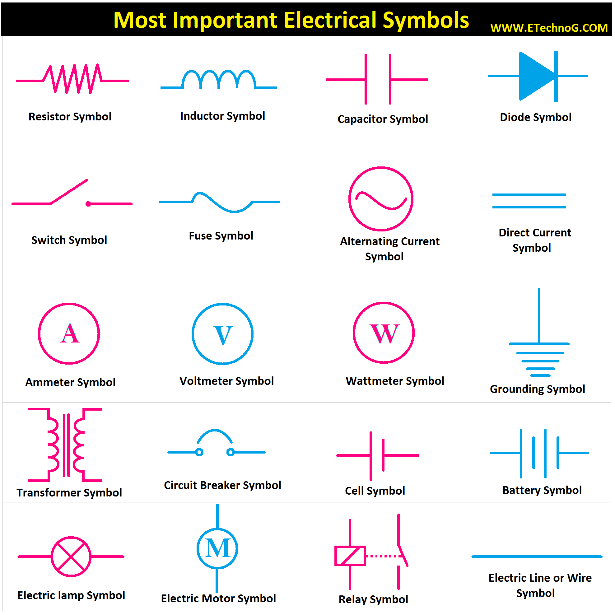
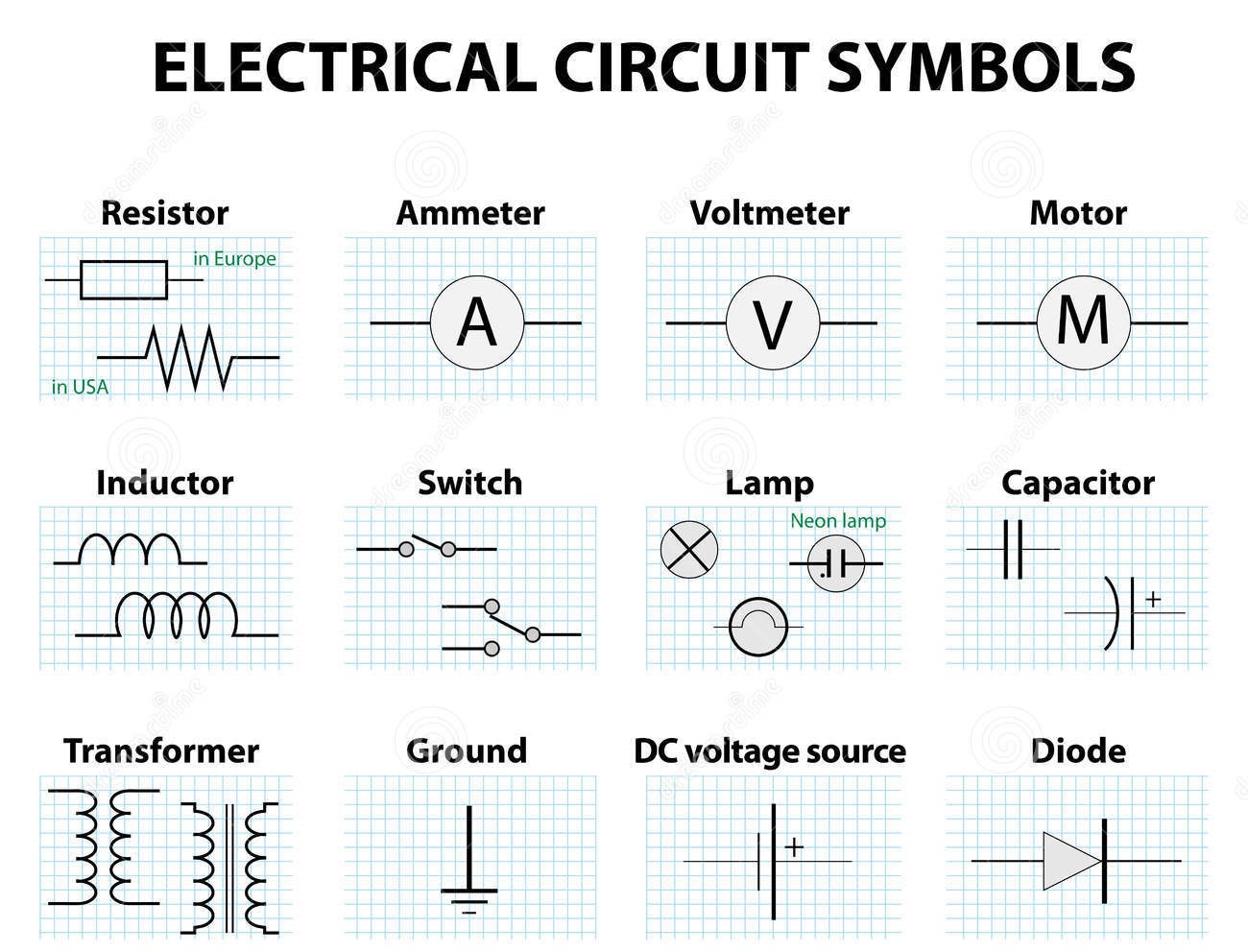
A simple example is the symbol for a resistor, a component that restricts the flow of current. It's depicted as a zigzag line. Another example is the switch, represented by a line with a break and an arrow indicating the opening or closing action.
Benefits of understanding electrical symbols include: 1) Accurate circuit design: Symbols ensure clear communication of components and connections. 2) Efficient troubleshooting: Symbols help identify faulty components quickly. 3) Safe installation and maintenance: Understanding symbols prevents miswiring and potential hazards. For example, recognizing the symbol for a ground connection is crucial for safety.
Creating a simple circuit, like a light switch controlling a bulb, requires understanding and applying the symbols for a battery, switch, wires, and a lamp. Connecting these symbols correctly on a diagram translates directly to the physical wiring.
Advantages and Disadvantages of Standardized Electrical Symbols
| Advantages | Disadvantages |
|---|---|
| Universal understanding | Requires initial learning |
| Facilitates collaboration | Potential for misinterpretation if not used correctly |
| Improved safety | Constant updates and additions require ongoing learning |
Best practices include consulting standardized symbol references, using clear and organized diagrams, and labeling components clearly. Real examples include home wiring diagrams, automotive electrical systems, and industrial control circuits.
Challenges include keeping up with new symbols and variations in standards. Solutions involve regular training and using up-to-date resources.
FAQs: 1. Where can I find a comprehensive list of electrical circuit symbols? - IEEE and IEC websites. 2. What is the symbol for a capacitor? - Two parallel lines. 3. How do I represent a diode? - A triangle with a line. 4. What's the importance of polarity in symbols? - Indicates direction of current flow. 5. How do I learn more about electrical diagrams? - Textbooks and online resources. 6. Are there software tools for drawing circuit diagrams? - Yes, numerous CAD software options exist. 7. How are symbols used in troubleshooting? - They guide technicians to faulty components. 8. What's the difference between a schematic and a wiring diagram? - Schematics show the logical flow; wiring diagrams show physical connections.
Tips: Practice drawing and interpreting diagrams regularly. Use software tools to create and simulate circuits.
In conclusion, electrical circuit symbols form the foundation of electrical communication. From simple household circuits to complex industrial systems, these symbols ensure clarity, efficiency, and safety. Understanding their history, significance, and practical application empowers individuals to design, build, and maintain electrical systems effectively. Embracing best practices, staying up-to-date with evolving standards, and utilizing available resources will ensure accurate interpretation and application of these vital symbols. Mastering these symbols opens the door to a deeper understanding of the fascinating world of electricity, enabling you to contribute to technological advancements and innovative designs. Take the time to explore the resources available, practice reading and drawing circuit diagrams, and delve into the world of electrical engineering. Your understanding of these symbols will not only enhance your technical skills but also contribute to a safer and more efficient electrical world.
Discover the charm of lake wissota inns
Creamy mushroom behr paint a warm neutral for your home
Garage floor game changer garage floor mats


