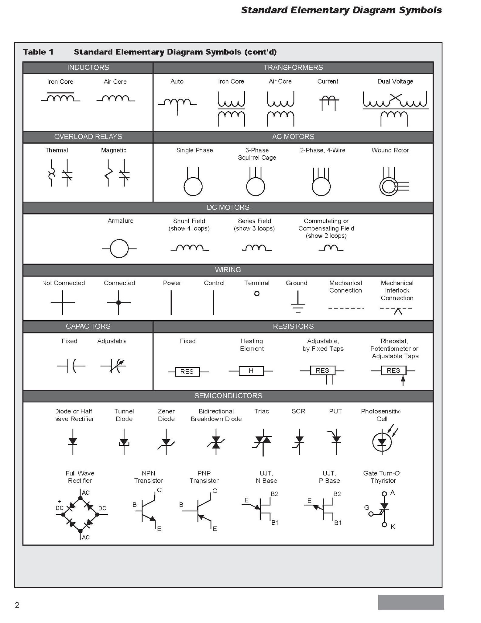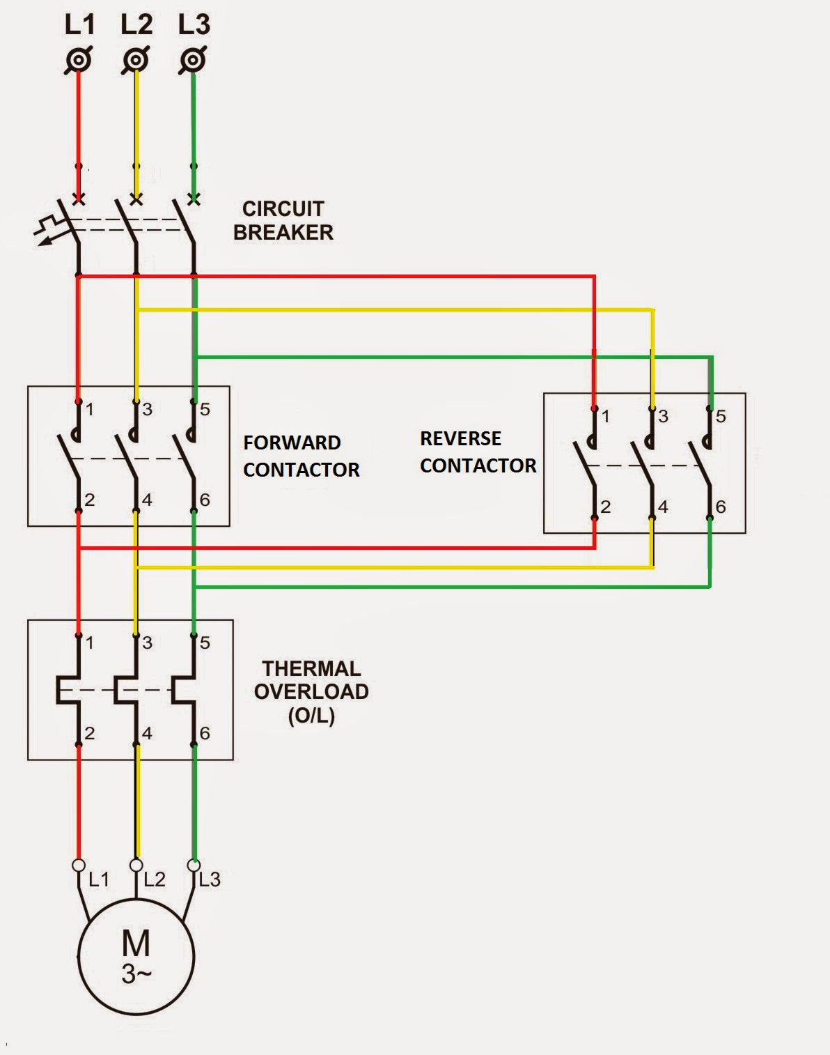
Imagine a tiny switch controlling a powerful machine. That, in essence, is the power of a relay. But to harness this power effectively in electrical control circuits, understanding the language of relay symbols is paramount. These symbols, a shorthand for complex electrical operations, are the key to designing, interpreting, and troubleshooting any system involving relays. This article explores the fascinating world of relay symbols, their significance, and practical applications.
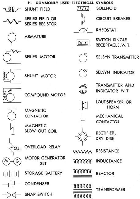
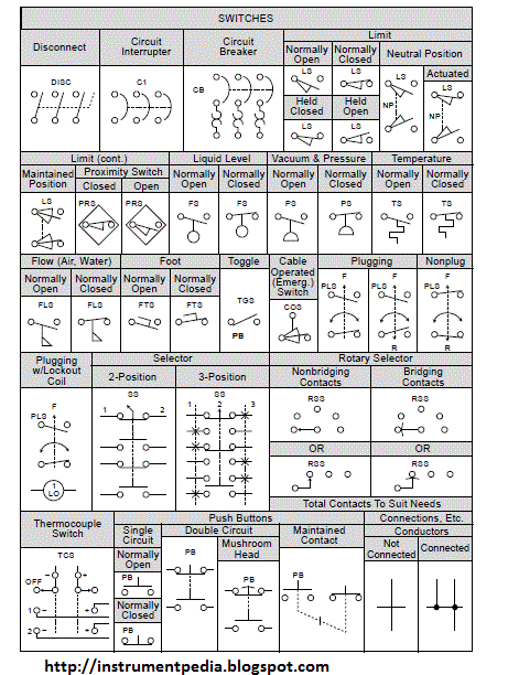
Relay symbols represent a crucial bridge between the abstract design of an electrical control system and its physical realization. They provide a visual representation of the relay's function within the circuit, allowing engineers and technicians to communicate effectively. Without a standardized set of symbols, interpreting complex wiring diagrams would be a nightmare, leading to errors and inefficiencies. Mastering these symbols is therefore essential for anyone working with electrical control systems.
The history of relay symbols is intertwined with the development of electrical engineering itself. As electrical systems grew in complexity, the need for a standardized way to represent their components became evident. Over time, various organizations, including the International Electrotechnical Commission (IEC), contributed to the development of the symbols we use today. These standardized symbols ensure clarity and prevent misinterpretations across different projects and industries.
The importance of relay control in electrical systems cannot be overstated. Relays enable the control of high-power circuits with low-power signals, providing isolation and safety. They are essential components in a wide range of applications, from industrial automation and power distribution to household appliances and automotive systems. Understanding how these relays are represented symbolically is vital for designing, operating, and maintaining these systems.
One of the main issues related to relay symbols is the potential for confusion if not properly understood. Different standards might use slight variations of symbols, and older diagrams may employ outdated representations. Therefore, ensuring familiarity with the relevant standard and context is crucial for accurate interpretation. Misinterpreting a relay symbol can lead to faulty wiring, malfunctioning equipment, and even safety hazards.
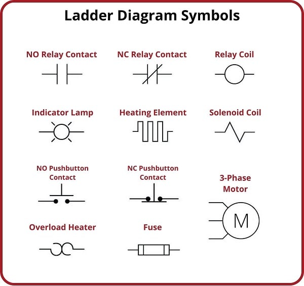
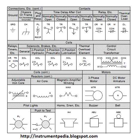
A relay, in its simplest form, is an electrically operated switch. It uses a small current to energize an electromagnet, which then closes or opens contacts, controlling a separate, often higher-power circuit. The relay symbol represents this functionality graphically, depicting the coil, contacts, and their interconnections. Different symbols denote different types of relays, such as normally open (NO) and normally closed (NC) contacts, latching relays, and time-delay relays.
Benefits of understanding relay symbols include efficient circuit design, simplified troubleshooting, and improved communication between engineers and technicians. For example, a technician troubleshooting a motor control circuit can quickly identify a faulty relay by interpreting its symbol on the wiring diagram. This saves valuable time and minimizes downtime.
To effectively implement relay control, a systematic approach is necessary. This includes selecting the appropriate relay type, understanding the control logic, and correctly interpreting the symbols on the wiring diagram. Successful implementation ensures safe and reliable operation of the electrical system.
Advantages and Disadvantages of Relay Control
| Advantages | Disadvantages |
|---|---|
| Electrical Isolation | Slower switching speed compared to solid-state devices |
| Cost-effective for high-power switching | Contact wear and potential failure |
| Simple implementation | Can generate electrical noise |
Best Practices for Implementing Relay Symbols: 1. Adhere to relevant standards (e.g., IEC). 2. Clearly label all symbols. 3. Use consistent symbology throughout the diagram. 4. Ensure proper documentation. 5. Verify symbol interpretation with colleagues.
Frequently Asked Questions: 1. What does a normally open contact symbol represent? 2. How is a latching relay depicted symbolically? 3. What are the common standards for relay symbols? 4. How can I identify a time-delay relay symbol? 5. What is the difference between a normally open and normally closed contact symbol? 6. Where can I find resources for learning more about relay symbols? 7. How do relay symbols help in troubleshooting electrical circuits? 8. What are some common mistakes to avoid when interpreting relay symbols?
Tips and tricks for working with relay symbols include using software tools for creating and managing electrical diagrams, referencing standardized symbol libraries, and practicing interpretation with real-world examples. These practices can enhance your proficiency and minimize errors.
In conclusion, relay symbols are the fundamental building blocks of electrical control system design. They provide a concise and standardized language for representing the functionality of relays within a circuit. Understanding these symbols is crucial for anyone involved in the design, installation, operation, and maintenance of electrical control systems. From simplifying complex diagrams to enabling efficient troubleshooting, mastery of relay symbols empowers engineers and technicians to create robust, safe, and reliable electrical systems. The ability to accurately interpret and apply these symbols is not just a technical skill, but a cornerstone of effective electrical engineering practice. Invest the time to learn them well, and unlock the full potential of relay control in your electrical projects. By prioritizing a deep understanding of these symbolic representations, you contribute to the safety, efficiency, and reliability of the systems you work with.
The alchemy of automotive transformation exploring the art of vinyl wrapping
Unlocking potential with dr su yun chungs methodology
Decoding the chevy 6 lug bolt pattern your guide to wheel fitment

