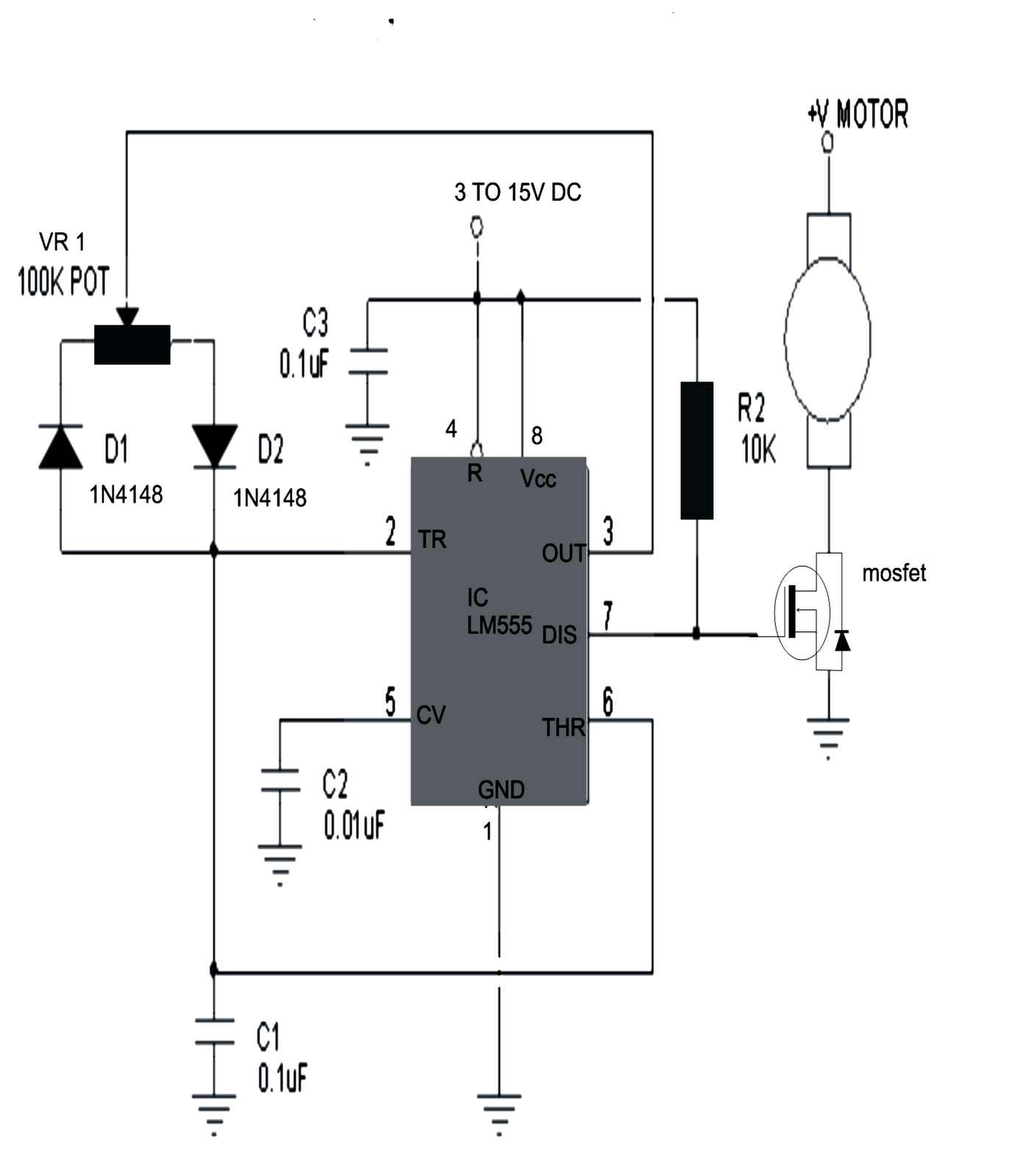
Ever wondered how devices, from electric cars to robotic arms, achieve precise and controlled movements? The secret often lies within a seemingly simple yet powerful tool: the DC motor control schematic diagram. This visual representation acts as a roadmap, guiding engineers and hobbyists alike in harnessing the full potential of direct current motors. Understanding these diagrams is crucial for anyone working with automated systems, robotics, or even simple electronic projects involving motor control.
DC motor control circuits, depicted in schematic diagrams, allow us to manipulate a motor's speed, direction, and torque. They bridge the gap between a power source and the motor, providing a controlled flow of electricity. This control is vital in countless applications, from precisely positioning a telescope to regulating the speed of a conveyor belt. Without these control mechanisms, motors would simply spin at a constant, uncontrolled speed, limiting their usefulness.
The history of DC motor control diagrams is intertwined with the development of electrical engineering itself. Early diagrams were simple, often involving basic switches and resistors. As technology progressed, so did the complexity of these diagrams, incorporating transistors, integrated circuits, and microcontrollers. This evolution has led to more precise and sophisticated control methods, enabling a wider range of applications and improved efficiency.
One of the main issues related to DC motor control circuit design is achieving optimal performance while minimizing power consumption and heat generation. Careful component selection and circuit design are crucial to balance these factors. Another challenge is ensuring safety and reliability, especially in high-power applications. Proper grounding, overcurrent protection, and thermal management are essential considerations when implementing a DC motor control system.
A DC motor control schematic diagram uses symbols to represent various electrical components, such as transistors, diodes, resistors, and capacitors. These symbols are connected by lines that represent the flow of current. The diagram provides a visual representation of the circuit's structure and how the components interact to control the motor. For a simple example, a basic DC motor control circuit might involve a transistor acting as a switch to control the current flowing to the motor. By varying the signal to the transistor, the motor's speed can be adjusted.
One key benefit of using a DC motor control schematic is the ability to precisely control motor speed. This is achieved through techniques like Pulse Width Modulation (PWM), where the motor is rapidly switched on and off, effectively controlling the average voltage and thus the speed. Another advantage is the ability to reverse the motor's direction, achieved by switching the polarity of the voltage applied to the motor terminals. Finally, these diagrams provide a clear and concise way to troubleshoot and diagnose problems within the control circuit, making maintenance and repair easier.
A step-by-step guide to reading a DC motor control diagram typically involves identifying the power source, tracing the flow of current through the various components, and understanding the function of each component. Resources such as online tutorials, textbooks on electrical engineering, and specialized software can assist in this process.
Advantages and Disadvantages of Using DC Motor Control Schematic Diagrams
| Advantages | Disadvantages |
|---|---|
| Precise speed control | Can be complex for beginners |
| Reversible direction control | Requires knowledge of electronic components |
| Simplified troubleshooting | Potential for errors in design or implementation |
Best practices for implementing a DC motor control schematic include selecting appropriate components for the intended application, ensuring proper grounding and overcurrent protection, and thoroughly testing the circuit before deployment.
Real-world examples of DC motor control circuits can be found in electric vehicles, industrial automation systems, robotics, and consumer electronics like printers and DVD players.
Challenges in DC motor control often involve dealing with noise, interference, and thermal management. Solutions include using appropriate filtering techniques, proper shielding, and heatsinks.
FAQs about DC motor control diagrams might cover topics such as how to choose the right motor driver, how to implement PWM speed control, or how to troubleshoot common problems.
Tips and tricks for working with DC motor control schematics include using simulation software to test the circuit before building it, using breadboards for prototyping, and carefully documenting the circuit design.
In conclusion, the DC motor control schematic diagram is an indispensable tool for anyone working with DC motors. It provides a visual representation of the circuit, enabling precise control over the motor's speed, direction, and torque. Understanding these diagrams opens up a world of possibilities for designing and implementing automated systems, robotics, and countless other applications. From simple projects to complex industrial machinery, mastering the art of DC motor control is a valuable skill for engineers and hobbyists alike. By studying these diagrams, exploring available resources, and following best practices, you can unlock the full potential of DC motors and bring your projects to life. By understanding the fundamentals of DC motor control and the intricacies of schematic diagrams, you can confidently design and implement efficient, reliable, and safe motor control systems. Embrace the power of these diagrams and embark on a journey of innovation and exploration in the world of electromechanical systems.
Refreshing your home with sherwin williams paint in the uk
Mastering four digit addition with carryover
Unlocking the enigma navigating the new toyota rav4 price landscape


